Displays for ESP32-P4
ESP32-P4 drives MIPI DSI panels over 2 lanes at up to 1.5 Gbps each, plus 8/16/24-bit parallel RGB and 8080 displays. Frame buffers for MIPI panels live in its in-package PSRAM.
Which display interfaces does ESP32-P4 support?
| Interface | Practical max resolution | Notes |
|---|---|---|
| MIPI DSI | Up to 1080p (Espressif) | 2 lanes × 1.5 Gbps; panel must support 2-lane mode |
| RGB parallel | — | 8/16/24-bit via LCD_CAM; frame buffer in PSRAM |
| 8080 parallel | — | 8/16/24-bit via LCD_CAM; for panels with their own GRAM |
| SPI | — | GP-SPI2 / GP-SPI3 for small status panels |
Reference modules for ESP32-P4
Matched by interface and resolution. We send a test report only for modules we have run on this board; ask if you need one.
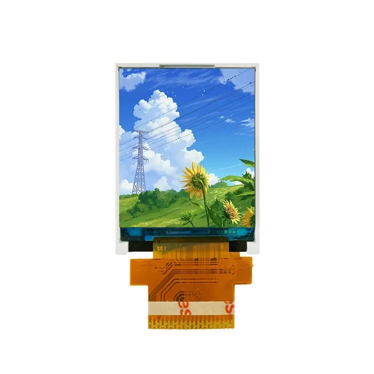
1.77" 128×160 TFT LCD, MCU (PJ177Z12)
- Size
- 1.77"
- Resolution
- 128×160
- Driver IC
- ILI9163V
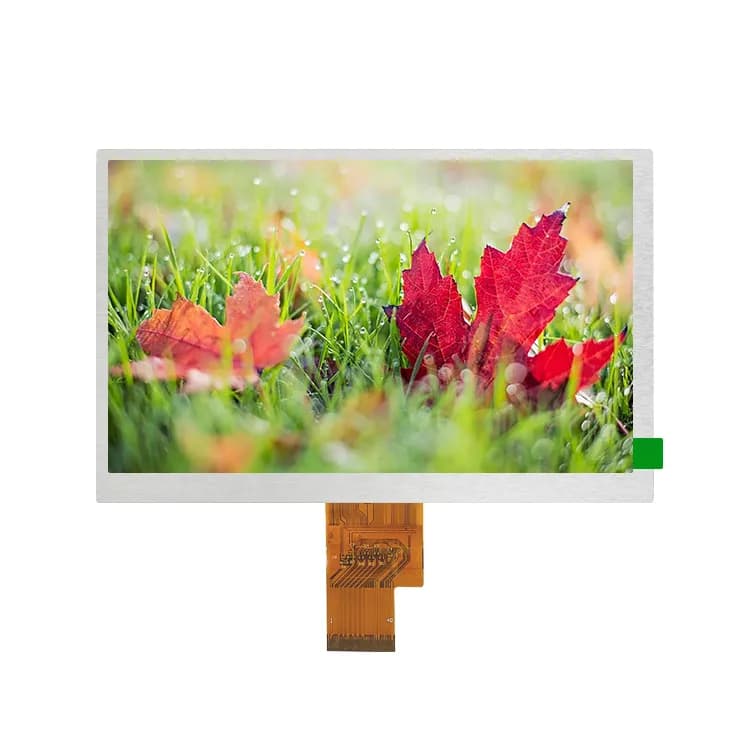
8" 800×1280 IPS TFT LCD, MIPI DSI (PJ8002I01-26H31P200)
- Size
- 8"
- Resolution
- 800×1280
- Brightness
- 200 nits
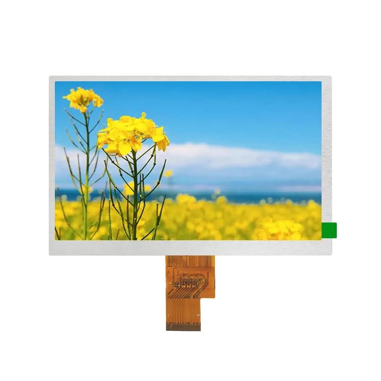
7" 800×480 IPS TFT LCD, RGB (PJ7004I38-57H40P1000)
- Size
- 7"
- Resolution
- 800×480
- Brightness
- 1000 nits
What the ESP32-P4 offers for displays
The ESP32-P4 datasheet (v0.7) lists two display paths:
- MIPI DSI: 2 data lanes at up to 1.5 Gbps each, compliant with D-PHY v1.1. Input formats RGB888, RGB666, RGB565, YUV422, YUV420 and grey; output formats RGB888, RGB666 and RGB565. The panel is driven in video mode, so it needs no frame memory of its own.
- LCD_CAM: 8, 16 or 24-bit parallel output in RGB, MOTO6800 or I8080 format, on any GPIOs through the GPIO matrix.
For graphics it adds a 2D-DMA controller and a pixel-processing accelerator (PPA) that rotates (0°, 90°, 180°, 270°), scales, mirrors and alpha-blends images. Unlike the ESP32-S3, which has no MIPI DSI, the P4 can drive the MIPI DSI panels used in phones and tablets.
Lane count: check this first
Two lanes is the limit. Many 7″–10.1″ MIPI panels are designed for 4 lanes; some of them can be configured for 2, many cannot. Before you order samples, check the lane options in the panel datasheet and the init sequence the vendor supplies for 2-lane mode.
Bandwidth and frame buffers
At 60 Hz in RGB888 (24 bits per pixel), the pixel data alone is:
- 480×640: about 0.44 Gbps, frame buffer 900 KB
- 1024×600: about 0.88 Gbps, frame buffer 1,800 KB
- 720×1280: about 1.33 Gbps, frame buffer 2,700 KB (2.64 MB)
- 800×1280: about 1.47 Gbps, frame buffer 3,000 KB
- 1920×1080: about 2.99 Gbps, frame buffer about 5.9 MB
Two lanes carry up to 3 Gbps, and the panel also needs blanking periods, so 1080p at 60 Hz in RGB888 has almost no headroom; RGB565 cuts the data by a third. Every one of these frame buffers is larger than the 768 KB of on-chip L2MEM, which is why the frame buffer sits in PSRAM: ESP32-P4 chips have 16 MB (ESP32-P4NRW16X) or 32 MB (ESP32-P4NRW32X) in the package.
Bring-up checklist in ESP-IDF
The ESP-IDF MIPI DSI LCD driver sets up a display in three steps:
esp_lcd_new_dsi_bus()creates the bus and initialises the D-PHY: setnum_data_lanes(2) andlane_bit_rate_mbps.esp_lcd_new_panel_io_dbi()opens the command channel; the panel's controller driver (for exampleesp_lcd_new_panel_ili9881c()) sends the init sequence over it.esp_lcd_new_panel_dpi()starts the video stream:dpi_clock_freq_mhz(the pixel clock),in_color_formatandout_color_format,num_fbsand thevideo_timingporches from the panel datasheet.
Two things catch people out:
- D-PHY supply. The MIPI D-PHY needs a dedicated 2.5 V supply on
VDD_MIPI_DPHY. It can come from the P4's internal adjustable LDO, which has to be set to 2.5 V before the DSI driver starts. - Pixel clock. ESP-IDF notes that a higher pixel clock gives a higher refresh rate but may cause flickering if the DMA bandwidth is not enough. If the image tears or flickers, lower
dpi_clock_freq_mhzfirst.
To copy bitmaps faster, the driver can use the 2D-DMA (esp_lcd_dpi_panel_enable_dma2d()).
Panels and touch
Espressif's ESP32-P4-Function-EV-Board pairs the P4 with a 7″ 1024×600 MIPI DSI capacitive touch screen through an LCD adapter board. M5Stack Tab5 units made before 14 October 2025 use an ILI9881C with a separate GT911 touch controller; later units use an ST7123 or ST7121 display-and-touch controller, and the init sequences are not interchangeable. Many capacitive panels use a GT911 touch controller, which answers at I2C address 0x5D or 0x14 depending on the INT level at reset.
Our MIPI DSI models include a 3.5″ 480×640, a 4.99″ 720×1280 IPS with ILI9881D and an 8″ 800×1280 IPS. Their lane configuration is confirmed per project: send us the board you use and we check 2-lane operation and the init sequence before samples.
Frequently asked questions
Can ESP32-P4 drive a 4-lane MIPI DSI display?
Only if the panel can also run on 2 data lanes. The ESP32-P4 MIPI DSI interface has 2 lanes at up to 1.5 Gbps each. Check the lane options in the panel datasheet; some 4-lane panels have a 2-lane mode, many do not.
What resolution can ESP32-P4 drive over MIPI DSI?
Espressif quotes up to 1080p. At 60 Hz in RGB888, 720×1280 needs about 1.33 Gbps of pixel data and 1024×600 about 0.88 Gbps, well inside the 3 Gbps of two lanes. 1920×1080 at 60 Hz in RGB888 needs about 2.99 Gbps before blanking, so it leaves almost no headroom.
Does ESP32-P4 need PSRAM for a MIPI display?
In practice, yes. A MIPI panel has no frame memory of its own in video mode, so the P4 keeps the frame in RAM: 720×1280 in RGB888 is 2.64 MB and even 480×640 is 900 KB, more than the 768 KB of on-chip L2MEM. ESP32-P4 chips carry 16 or 32 MB of PSRAM in the package.
Sources
Not sure which display fits your design?
Send us your size, interface and host processor. A display engineer replies within 12 hours with 2–3 options, datasheets and init code. Samples from 1 pc.